No, we've got Airthings at home
The need for air sensing
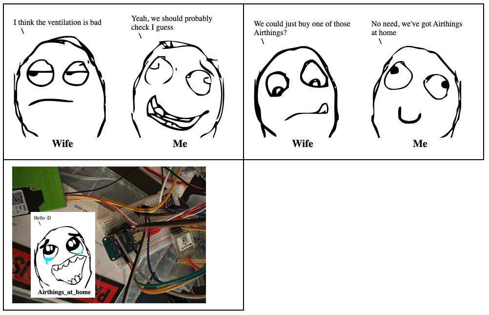
I had a conversation with my wife about ventilation that went something like this:
I have a soft spot for buying sensors and gadgets at night when I’m supposed to go to sleep. Always thinking that “Oh, this could be a cool addition If I ever do that project idea”. I love the idea of making IOT devices myself as they are often cheaper and much better at privacy and security as there is no cloud exposure. I was however a bit reluctant to embark and what I expected to be a steep learning curve, but I was in for a surprise. I found ESPHome which is an amazing platform for building IoT devices, and it has support for pretty much all the sensors and micro controllers I have stashed away. So the process was actually very straight forward! I know it’s more fun to read about failures and frustrations, but I’m preparing my adventure with a smart cat flap for that. Sometimes we have to treasure the wins! :D
The Parts
- D1 Mini # The brain aka Micro Controller
- SPS30 # The particle sensor
- Senseair S8 # The CO2 sensor
- BME280/BMP280# Combined Temp/Humidity/Pressure sensor
These components were all in my electronics stash, and most of them were a perfect fit for the task. Except for the last sensor, which isn’t actually made for sensing temperature, but does it as a way of calculating relative humidity. And waiting for a new sensor did not seem like an option.
It was time to get the breadboard and some jumper wires and get this ting connected. A breadboard is basically just a “plug and play” board which let’s you connect components easily without having to solder them in place. As you can see from the memeified picture at the top, it wasn’t pretty. But at this stage that’s not the point. Instead it’s time to start creating the configuration for ESPHome and test if all of these components work.
Proof of Concept
So first we start by creating a configuration file for ESPHome, with something like this:
esphome:
  name: airmon_stue

esp8266:
  board: d1_mini
We gave our device a name, and identified what model of microprocessor we’re using.
uart:
  rx_pin: GPIO14
  tx_pin: GPIO16
  baud_rate: 9600
Then we tell ESPHome that there is a device connected which will send us data on GPIO 14 and we can send it data on GPIO16. The GPIO’s are just the connection ports on the micro controller that we are using. UART stands for Universal Asynchronous Receiver/Transmitter and it’s a protocol that allows devices to communicate. This is old school serial communication and data is sent one bit at the time. The baudrate determines the speed of communication. So with this configuration we can talk to the Sensair CO2 sensor. This is an extremely common way to connect to devices like this, but if you have many devices you need many GPIO pins as the connection is always one to one.
i2c:
  sda: GPIO4
  scl: GPIO5
  scan: true
Next we configure the I2C, or Inter-Integrated Circuit, which is another protocol that allows devices to communicate over two wires. This one is not asynchronous though like UART, and requires us to use the dedicated i2c ports (4 and 5) on the micro controller. There are two wires to connect, one is for data and one is for a clock. The clock let’s the connected devices know when they can send data, so with this protocol we can connect multiple devices together without them speaking at the same time. Saving our precious IO ports! In our case both the Particle sensor and the Temp sensor connect this way.
sensor:
  - platform: senseair
    co2:
      name: "Airmon Stue CO2"
    update_interval: 60s
  - platform: bme280
    temperature:
      name: "Airmon Stue Temperature"
      oversampling: 16x
    pressure:
      name: "Airmon Stue Pressure"
    humidity:
      name: "Airmon Stue Humidity"
    address: 0x76
    update_interval: 60s
  - platform: sps30
    pm_1_0:
      name: "Airmon Stue PM <1µm Weight concentration"
      id: "airmon_stue_PM_1_0"
    pm_2_5:
      name: "Airmon Stue PM <2.5µm Weight concentration"
      id: "airmon_stue_PM_2_5"
    pm_10_0:
      name: "Airmon Stue PM <10µm Weight concentration"
      id: "airmon_stue_PM_10_0"
    pm_size:
      name: "Typical Particle size"
      id: "pm_size"
    address: 0x69
    update_interval: 10s
Now that we’ve defined how to communicate with the sensors we can define the sensors data. Here we’ve setup the CO2 sensor using the “sensair” platform and set a name for the sensor. We do the same for the Temp/Humidity/Pressure sensor and finally the particle sensor. Each of them with their specific platform which is basically ESPHomes built in support or driver if you’d like for that particular device.
logger:

api:
  password: "<some password>"

ota:
  password: "<not the same password>"

wifi:
  ssid: "My_dedicated_IOT_wifi"
  password: "<yet another password>"
We add an empty logger directive to enable logging and set a password for the device API endpoint. This allows Home Assistant to communicate with the device. The same goes for the OTA password for when we want to upgrade/reconfigure the device. Finally we tell it how to connect to our IOT wifi network.
Let’s deploy some firmware
Now we just need to connect to the device using usb, and issue the magic command
esphome run config.yaml
This will cause ESPHome to compile the firmware, package it with our configuration and upload it to the micro controller. But alas, only the UART connected CO2 sensor worked. I thought maybe this was due to the particle sensor drawing to much power, since I now had 3 sensors and a micro controller powered through usb. But adding a dedicated 5v power supply changed nothing unfortunately.
After reading up on I2C however, the problem was quite obvious because the protocol requires a stable signal to work. A signal going over the wire can be 1 of 3 states.
- On/High/+
- Off/Low/-
- Floating between the tow
I2C requires that both wires should be high when not sending data. When a device wants to send data, they connect the signal to ground, which will pull it Low, or the Off state. But in my case the signal was never stable in the high position, it was floating between high and low, which caused all communication to break down.
The solution was to add a cable from the 3.3v power port on the micro controller to both of the I2C cables though a pull up resistor to pull them high when not in use. 3.3v is what the micro controller will recognize as high in this case. With the pull up resistor in place, both signals were high when not in use, and communication could finally happen giving this output on the command line:
[10:05:20][D][sensor:093]: 'Airmon Stue PM <1µm Weight concentration': Sending state 0.43919 µg/m³ with 2 decimals of accuracy
[10:05:20][D][sensor:093]: 'Airmon Stue PM <2.5µm Weight concentration': Sending state 0.70996 µg/m³ with 2 decimals of accuracy
[10:05:20][D][sensor:093]: 'Airmon Stue PM <4µm Weight concentration': Sending state 0.91270 µg/m³ with 2 decimals of accuracy
[10:05:20][D][sensor:093]: 'Airmon Stue PM <10µm Weight concentration': Sending state 1.01576 µg/m³ with 2 decimals of accuracy
[10:05:20][D][sensor:093]: 'Typical Particle size': Sending state 0.85657 µm with 0 decimals of accuracy
...
[10:05:27][D][sensor:093]: 'Airmon Stue Temperature': Sending state 31.49000 °C with 1 decimals of accuracy
[10:05:27][D][sensor:093]: 'Airmon Stue Pressure': Sending state 961.61102 hPa with 1 decimals of accuracy
[10:05:27][D][sensor:093]: 'Airmon Stue Humidity': Sending state 25.32520 % with 1 decimals of accuracy
...
[10:05:40][D][sensor:093]: 'Typical Particle size': Sending state 0.85347 µm with 0 decimals of accuracy
[10:05:41][D][senseair:059]: SenseAir Received CO₂=741ppm Status=0x00
[10:05:41][D][sensor:093]: 'Airmon Stue CO2': Sending state 741.00000 ppm with 0 decimals of accuracy
Success! :D
Cleaning up the wires
Since everything is now working it was time to move away from the horrible mess on the breadboard to a cleaner design. Some people design custom PCBs to mount their devices, but being in Norway there was no time to wait for that shipping (not to mention the import tax which would have doubled the price).
So instead I used some perfboards, which basically look like PCBs with holes everywhere. These holes allow us to solder devices and cables in place where we want them. It’s not as neat as a custom PCB, but it beats the breadboard.
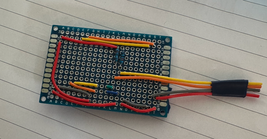
I made one mistake with the design above though, which I had to fix after assembling everything. The orange wire going from 13S to 13F should have gone all the way to 13D. But fortunately it wasn’t a big deal to change.
The tricky part here was that the Particle and CO2 sensor both required 5v while the Temp sensor wanted 3.3v. So everyone got 5v directly from the power supply, while the temp sensor got it’s 3.3v from the power output on the micro controller. The important part is that everyone shares the same ground!
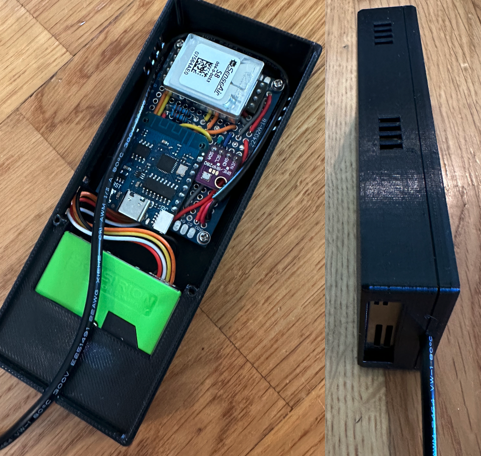
With all the components soldered in place and a 5v power supply added, we’re ready for housing which I slapped together using jsCad and printed. It’s not going to win any design awards, but it fits everything nicely and has ventilation holes for all the sensors. I jumped over to Home Assistant, added a new device to the ESPHome integration using the password from the config file and I could finally get some data. My plan was to have one sensor in our living room and one in the basement next to the 3d printer, so I kept both new sensors next to eachother for a few days to verify that they gave the same data.
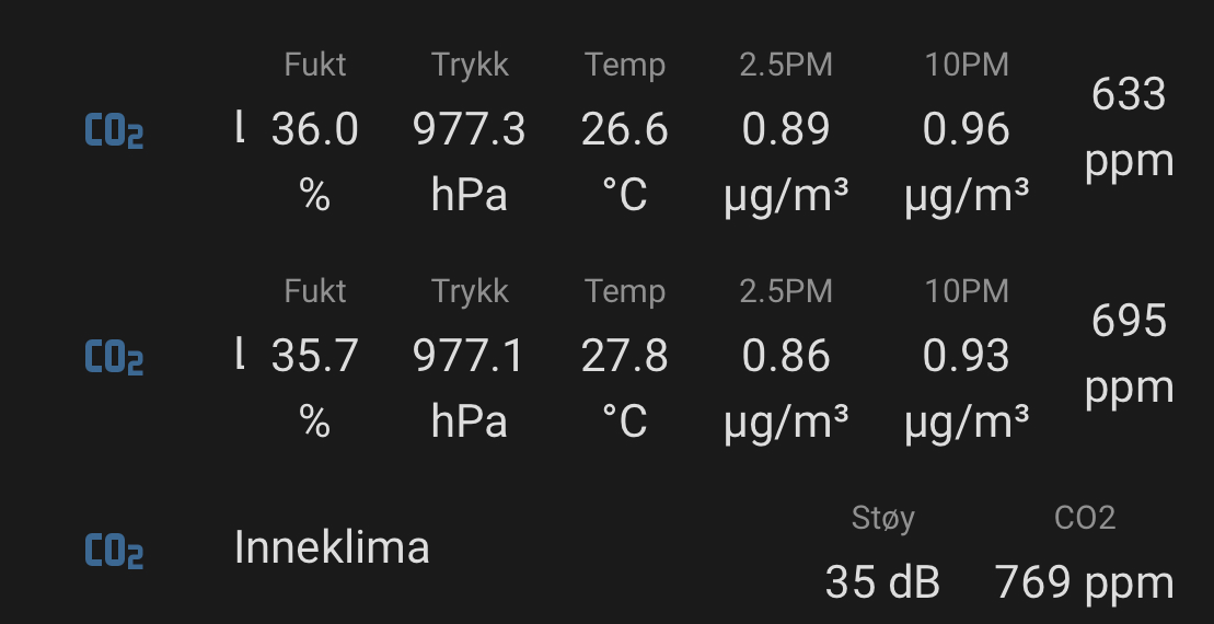
As you can see the two top lines are the new sensors, and the bottom decibel and CO2 are from my old Netatmo climate sensor. From what I have been able to figure out the Netatmo doesn’t actually measure CO2 but calculates it from other measurements, but it doesn’t seem to be far off from the Sensair sensors actually.
But the two new sensor seem to agree on everything, except the temp which I pretty much expected to not be accurate. I have other sensors around the house for that so to me it’s not a big deal.
Wrapping up
Now I’m planning some new dashboards for air quality in Home Assistant and I’ve already added an automation to open more windows if the air quality get’s bad. I had also planned on running a controlled test of the particle sensor by lighting a match next to it, but we needed to get a fire going in the fireplace and that absolutely verified that it was sensing particles. A tiny bit of smoke came into the room when I closed the door to the fireplace and the sensor immediately showed 50+ ug/m3.
Also; I actually wanted to add a Radon sensor on the basement device, but those were crazy expensive at around $300. So compared to the $140 I spent on parts for these two devices in total it was just not worth it to add the Radon sensor. Later I’m hoping to design some 3d printed ventilation duct’s with HEPA filters so I can use the CO2 and particle information to actually improve the ventilation. But you know, these things take time :P